Houston, TX |
This post will provide Detechtion Technologies’ recommended steps for troubleshooting Blowby and “Gauge Maintenance”. These two concepts, along with their possible causes, were discussed in detail in E-Tips 1.3 - 1.7.
Measuring the Heath of Gas Compression Cylinders
Blowby is a term used by Detechtion Technologies to quantify inefficiencies in the compression process. Blowby is an indication of the health and efficiency of the valves and piston rings inside every cylinder. In short, it is a measure of the number of molecules of gas that are being re-circulated and recompressed within a cylinder. As more gas is re-circulated and recompressed, the temperature rise across the cylinder increases, more horsepower is required and the cylinder’s capacity to compress gas decreases. The main causes of a Blowby flag on an Enalysis report are:
- Damaged or worn valves
- Worn piston rings
- Unaccounted pressure drops (ie. inter-stage)
- Clogged inlet suction filter (witches hats)
- High lube rates
- Improper valve springing
Unexpected Inputs from Monitored Parameters
Gauge Maintenance is the term used by Detechtion Technologies when the monitored compressor parameters are thermodynamically impossible according to the Enalysis software model. This occurs when the calculated expected discharge temperature is greater than the actual measured discharge temperature for a cylinder. On a Blowby trend, Gauge Maintenance presents as negative Blowby. However, while Blowby represents an inefficiency in the compression process, Gauge Maintenance indicates that something is not as expected. The following are the main causes of a Gauge Maintenance flag on an Enalysis report:
- Faulty Sensors / Infrared Guns
- Changes in Gas Composition
- Changes in Valve Model or Lift
- Recycled Gas
- Water-Cooled Cylinders
Note that some of the causes of Gauge Maintenance can also be causes of Blowby.
Troubleshooting Steps
Step 1: Confirm field data entered in Enalysis:
- Use temperature gun to confirm reported suction and discharge temperatures are an accurate representation of the true gas temperature at suction and discharge to each cylinder
- Identify the location of pressure sensors in relation to the cylinder
- Confirm pressures with local gauges, where possible
- For the infrared temperature gun:
- Confirm accuracy of temperature gun
- Confirm temperatures are taken off matte black paint and not bare metal
- Confirm emissivity setting = 0.96 – 1.00
Step 2a: For units with High Blowby:
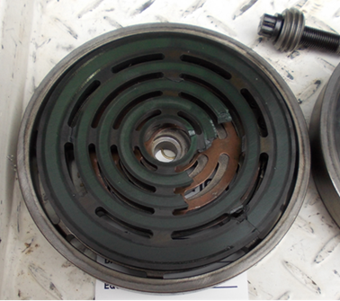
- Check for damaged or worn valves
- Check for worn piston rings
- Check for high or low lube rates
- Check for restrictions causing pressure drops between suction pressure reading and suction flange of cylinder
- Check for leaking piston rod packing cases
- Check for damaged VVCP
- Check for scored or damaged cylinder walls
- Check for improper valve springing for current operating conditions and gas composition
Step 3b: For units with Gauge Maintenance:
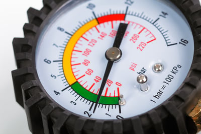
- Troubleshoot any faulty sensors from Step 1
- Confirm a recent gas analysis with the one in Enalysis
- Take a new gas analysis if there is no recent analysis
- Confirm if compression cylinders have auxiliary water for cooling
- Check if recycled gas is commingling with suction gas down stream of suction temperature reading
Step 4: Confirm hardware specifications and gas composition:
- Confirm valve lift and area
- Confirm process gas composition
- Confirm if cylinders are water-cooled
- Confirm cylinder suction and discharge orifice plate
- Confirm if valves have cushioning plates or other modifications
It is possible to streamline this troubleshooting through more detailed Enalysis of the variables and trends in the Enalysis report. But first, we need to increase your knowledge of compression. To assist you with this, compression fundamentals will be covered in future E-Tips.
Click here to read Enalysis Tip 1.9 - Compressor Field Data Entry with Fieldlink® now!

